Membrane Switch Manufacturer's Complete Guide to Membrane Switch & Graphic Overlay Design
- Larry Owens
- Sep 20, 2022
- 9 min read
Updated: Mar 7, 2023
Use this comprehensive membrane switch manufacturer's guide to successfully communicate design intent, environmental and electrical specifications for your membrane switch or graphic overlay design.
INTRODUCTION
Communication of design intent between design engineers and membrane switch manufacturers is critical. This design guide is a tool for communicating the requirements and specifications of your project to the engineering team at Industrial Print Technologies (IP Tech).
IP Tech’s engineers have prepared this membrane switch design guide to help you design a manufacturable membrane switch panel that will meet all of your electronic, geometric, and environmental requirements.
WHAT IS A MEMBRANE SWITCH?
A membrane switch is a custom switch electronic switching assembly is used to open and close the conducting path in an electrical circuit to control machines and devices, and requires at least one of the electronic contact layers to be made of a flexible substrate. Its assembled differently than a traditional mechanical switch: a membrane switch's construction consists of several thin layers that are bonded together using pressure-sensitive adhesives.

Each layer in a membrane switch assembly serving a specific and different purpose, when brought together in the assembly create a plug and play user-to-machine interface.
Membrane switches utilize the benefits of flexible printed electronics. These circuits are most commonly printed onto Polyester materials. The ink used for printing the circuit is usually filled with silver, or graphite and therefore conductive.
The ASTM defines a membrane switch as "a momentary switch device in which at least one contact is on, or made of, a flexible substrate."
COMMON APPLICATIONS OF MEMBRANE SWITCHES
Common applications and uses of membrane switch include microwave oven control panels, remote controls, entry keypads, etc. Tactile feedback of buttons can be provided by embossing the top layer or embedding tactile metal snap domes, polyester domes into the assembly, or forming the graphic layer into a dome shape that will have a tactile "snap" when pressed.
The benefits of membrane switches include ease of cleaning, sealing ability and their low profile. Membrane switch can be used together with other control systems such as touch screens, keyboards, lighting, and they can also be complicated like the membrane keyboards and switch panels in mobiles and computers. They are reliable, effective, low-cost user interfaces, suitable for a wide range of products, and available with many creative options.
Depending on industry and application, membrane switches are also referred to as membrane keyboards and membrane keypads.
LAYERS OF A TYPICAL MEMBRANE SWITCH
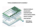
A membrane switch typically has 5 or more layers made of flexible substrate. Here is a typical or common membrane switch construction.

Graphic overlay: The top layer of a membrane switch is the graphic overlay. This layer serves as the user interface, as it will typically show the user how to operate the device. This layer will often be made by digitally printing or screen printing ink onto the back of a hard coated PET or polycarbonate substrate.
Spacer top adhesive: The spacer top adhesive layer typically goes beneath the graphic and adheres the graphic to the rest of the membrane switch.
Dome retainer: The dome retainer goes below the spacer top adhesive layer. The dome retainer layer holds the metal domes or shorting pads that will be used to activate the switch. This layer is typically made of thin, flexible PET.
Spacer adhesive: The spacer adhesive layer goes beneath the dome retainer. This layer includes ventilation cuts that allow air to flow when the tactile switches are actuated.
Circuit layer: Typically conductive inks are printed on thin flexible PET to make the circuit layer. Silver and carbon inks are most commonly used. Sometimes FPCs or PCBs are used instead. The circuit layer is what allows the membrane switch to function. When the switch is not actuated, the circuit is open and current does not flow. When the user activates the switch by pushing down on the metal dome or shorting pad, the circuit becomes closed and current is able to flow, triggering the appropriate response from the membrane switch.
Mounting adhesive: The bottom layer of a membrane switch is the mounting adhesive, which is used to attach the membrane switch to the desired application.
A membrane switch typically has 5 or more layers made of flexible substrate. Here is a typical or common membrane switch construction.
SELECTING THE RIGHT GRAPHIC OVERLAY MATERIAL
Common graphic overlay materials used are polyester and polycarbonate. These materials are available in a variety of finishes. Most always, graphic overlays begin as a clear material with the graphics usually printed on the reverse side (sub-surface printing) of the plastic. Selective textures are printed on the front side (top-surface printing) of the product to allow product designers match surface textures and finishes of the rest of their product or device.

Polycarbonate is commonly used because it’s easy to print on, die cut and emboss, making it cost-effective. The disadvantage of polycarbonate is that it begins to show signs of wear sooner that other materials. While polycarbonate is still used for certain applications, the life cycle data shows that it begins to wear as early as 40,000 cycles. Polyester shows no signs of wear at 100,000 cycles. Polyester is a material with a superior life cycle and chemical resistance properties.
Both polyester and polycarbonate are available with a variety of textures and hard coats. Keep in mind, glossy materials are highly susceptible to scratching, and should be hard-coated for protection.
PRINTING REQUIREMENTS & GRAPHIC OVERLAY DESIGN
ARTWORK & DRAWINGS:
Most customers supply an electronic file in .ai (Adobe Illustrator) form or other vector graphics program. IP Tech also offers design and engineering services if needed. All drawings should specify type styles, colors, and indicate sizes and locations of all graphics. It is recommended to outline all fonts, and to supply a pdf file in addition to the native file format. We accept DXF or DWG files for mechanical drawings and numerous graphics formats including Adobe Illustrator and Corel Draw. It is also recommended to supply a pdf file of the drawing. Proofs of all artwork will be provided for approval prior to printing.
COLORS:
It is possible to specify colors by providing a reference from either the PMS (Pantone Matching System) or any other color matching system. Samples of colors to match can also be provided in many forms. For example: existing labels, plastic housings, color chips or painted metal work. If you have an overlay being digitally printed, IP Tech can supply a sample for your approval. Digital printing will have its own set of specifications depending on the process selected by the designers at IP Tech, its best to talk with us about digital printed overlays before sending files.
PREMASKING
Graphic Overlays and Membrane Switch Graphic Layers, with windows for LED/LCD readouts that can be scratched during your assembly processing are often provided with a printed pre masking to protect it until the product is ready for use. We can provide peel tabs and removable masking solutions where the end user removes the masking before use.
HARD COATING & TEXTURING
The most durable textured hard coatings are those that are cured by exposure to ultraviolet light. These coatings are called UV hard-coats or textures. Hard coats or textures can be added when printing the graphic overlay top surface in selective areas, thus creating visual effects for windows and enhancing graphics. Many overlay materials come with a hard coat on the surface and textures can be selectively applied for the same visual results.
EMBOSSING
In many applications it is desirable to emboss or hydroform the keys of a switch. “Pillow Embossing” is used to describe keys that are raised and flat on the top. “Rail Embossing” is used to describe raising only the border of a key. Embossing is typically two-dimensional and .010” high. Hydroforming is used to obtain an emboss 2-3 times the material thickness.

Three-dimensional dies can also be built. Overlays can be formed with domes in them to provide a tactile feedback. Hydroforming tools are significantly more expensive than embossing tools but provide a more precise result when forming elements like poly tactile snap domes.
BACKLIGHTING OPTIONS
LED
Electroluminescent (EL)
Fiber Optic
ADHESIVE AND SPACER LAYERS
IP Tech uses mostly 3M™ materials in our membrane switch products. Membrane Switches are produced by laminating various layers of material together. Spacer layers for circuit separation are produced using a polyester layer sandwiched in between two adhesive layers. When specifying an adhesive, it is necessary to specify the adhesive used in the spacer layer, as well as the one which adheres the membrane switch to the component housing.
In most cases, flexible membrane switches are finished with 3M™ 467MP on the backside. This is an excellent adhesive for bonding to smooth metal and high surface energy plastic surfaces. For rougher surfaces, 3M™ 468MP adhesive is recommended. Some surfaces such as powder coated surfaces have lower surface energy. There are specific adhesives that are more appropriate for low surface energy applications.
CIRCUIT LAYERS
Membrane switches are usually printed with a screen printed silver-filled ink using the screen printing process. Carbon inks are use to create printed resistors or anti-oxidant protective coatings and durability. Carbon is most commonly used as an overprint of silver to protect against migration and wear in ZIF connector applications.
MECHANICAL & ENVIRONMENTAL SPECIFICATIONS
The following specifications are based on our typical membrane switch panels. The end result for a given customer part design will vary.
| Non-Tactile | Tactile Metal Dome | Tactile Polydome |
Key Travel | .005” - .020” .13 - .5 mm | 015” - .040” .38 – 1.0 mm | 015” - .040” .38 – 1.0 mm |
Operating Force | 80 – 340 g 3 – 12 oz | 110 – 1700 g 4 – 60 oz | 110 – 600 g 4 – 21 oz |
Actuation Life | > 1M cycles Up to 5M+ | > 1M cycles Up to 5M | > 1M cycles |
Operating Temp | -30 to 70°C -22 to 158°F | -30 to 70°C -22 to 158°F | -20 to 50°C -4 to 122°F |
Storage Temp | -40 to 70°C -40 to 158°F | -40 to 70°C -40 to 158°F | |
Humidity | 12 – 90% RH | 12 – 90% RH | 12 – 90% RH |
Minimum Tail Bend Radius | 0.063” (1.6 mm) - 25 cycles min at 20°C | 0.063” (1.6 mm) - 25 cycles min at 20°C | 0.063” (1.6 mm) - 25 cycles min at 20°C |
ELECTRICAL SPECIFICATIONS
The following specifications are based on our typical membrane switch panels. The end result for a given customer part design will vary.
| Non-Tactile | Tactile Metal Dome | Tactile Polydome |
Maximum Current Rating | 100 mA max | 100 mA max | 100 mA max |
Maximum Operating Voltage | 30 VDC max | 30 VDC max | 30 VDC max |
Maximum Operating Power | 1 W max | 1 W max | 1 W max |
Typical Operating Current | 1 to 30 mA | 1 to 30 mA | 1 to 30 mA |
Typical Operating Voltage | 3 to 12 VDC | 3 to 12 VDC | 3 to 12 VDC |
Closed Circuit Resistance | < 100 ohms typ | < 100 ohms typ | < 100 ohms typ |
Insulation Resistance | > 20 Meg | > 20 Meg | > 20 Meg |
Contact Bounce | < 10 mS | < 10 mS | < 10 mS |
Capacitance | < 30 pF | < 30 pF | < 30 pF |
Dielectric Withstand Voltage | > 500VDC | > 500VDC | > 500VDC |
SURFACE MOUNT COMPONENTS
Commonly surface mounted LEDs are incorporated into membrane switches. Depending on your application, the standard membrane switch may not thick enough to accommodate the package size of a surface mounted LED without embossing it to raise height over the LED.

Very often the overlay needs to be embossed or hydroformed to accommodate the surface mounted LEDs height. It's very important for our engineers to receive drawings showing how the LED’s interface with the electronics. This should be in the form of a schematic. Items to note are the electrical specifications of LED’s and resistors.
EMI/RFI SHIELDING
Many options are available for shielding membrane switches. Either carbon or silver can be printed over the top of the circuit to act as a shield or aluminum foil can be used. Carbon shields are less expensive than silver. A printed grid pattern is normally used to reduce cost and can be terminated to the circuit tail. Aluminum foil material is the most conductive shield available. However, it adds layers to the membrane switch construction. The foil will need a separate tail for ground connection.
Design of the shield on a membrane switch depends greatly on what performance is required for a given design. EMI shielding works by two mechanisms: reflection and absorption. Shielding, grounding, and EMI control in general is very complex and specialized, but a few basic principles can help as a guide: For a reflective shield to be most effective, its termination is very important. The ideal termination would be good electrical contact around the perimeter of the shield. Since this is often not practical, multiple wide, short tabs is the next best option.
If only a single termination point is available, that tab should be not more than 3 times a long as it is wide. In general, the lower the resistance (ohms per square) of the shield, the greater its effectiveness. In some cases, ESD only shields can still be effective even if higher resistance (such as with a printed carbon shield). Shields of this type will prevent a charge build-up but will offer little EMI or coupled ESD protection.
TAIL EXIT AND CONNECTOR GEOMETRY

The connector tail that exits a membrane switch most typically has a single row of traces on .100” (2.54mm) center to center. The tail can be printed and cut into nearly any shape for connection to the circuit board. A membrane switch tail can be connected to a circuit board with many different types of connectors designed for flex circuits. It can also be designed to work with a ZIF connector, or (Zero Insertion Force) connection.
We work with several types of connector brands and styles including AMP, Nicomatic and Molex. We can offer connectors ranging from .1" centers down to 1mm centers with our micro resolution screen printing capabilities. Typical membrane switch manufacturers only offer down to .05" centers.
The lowest cost connection is a ZIF connector. AMP and Molex both offer ZIF connectors. When using a ZIF connector the membrane switch tail is designed with exposed contacts on at the very end. The tail is then inserted the ZIF connector on the PCB on assembly. If your application is rugged, ZIF connectors are also available with locking mechanisms.
When using a ZIF connector you should specify the exact mating connector you will be mating the membrane switch tail to.
Male/Female Connectors: The most common approach to thin-film connections is through using Nicomatic or AMP male pins and female pins. Both are used extensively to interface to Control Boards, energy sources, wires and housings. The male is similar to the solder tab, but made to connect instead of to solder. The female has three or four sides, and provides robust connection.
MATRIX VS COMMON BUS
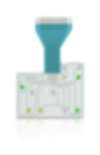
Designers can save valuable space by using a matrix layout vs a common bus. In this diagram you can see how more button location can be connected using less tracings by incorporating a matrix layout. Our engineers can work with you to develop the best pinout to achieve both unit price targets and performance.

CONCLUSION
To receive a quote for a membrane switch panels or graphic overlay printing contact IP Tech to learn more.

Download this complete guide in pdf print-friendly format here. Design Guide


